
The Virtual Pinball Machine
Installing the Components | Back to Intro | The Finished Game
Fan Wiring
This is the easiest part of all. If you buy computer case fans like I did, all you have to do is plug them into a matching power connector on the computer's power supply. Nothing to it.
Button and Plunger Wiring
Wiring is easier with the Mot-Ion controller (or whatever controller comes with the digital plungers these days) as opposed to using a programmable interface board like the IPac. Because the Mot-Ion controller is made specifically for pinball cabinets, the outputs on the board are labeled on the wiring diagram as to their function (left flipper, right flipper, start, exit, etc.). This makes it super-simple to figure out which connector goes where.
You really should buy some quick disconnects--most arcade buttons use 0.25" connectors. You could solder every connection, but that's a waste of time. It also makes it more difficult to replace a button should you ever need to do so. Strip about a quarter-inch of insulation off the wire, slide the connector on, and crimp it in place. I used pliers to do this, but I recommend finding a decent crimper. Using pliers is a real hand-buster.
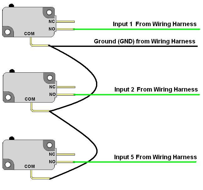
Beyond that, all you need to know is a little basic wiring. In my case, I simply looked at the way that the buttons were wired in one of my video games and emulated it. I drew up a diagram (in the photo gallery) to make it easy for you. Those of you with sharp eyes will see that I actually reversed the ground and live connections on my buttons. This is because the control panel on NBA Jam (which I was using as a guide) was wired that way. Wiring it backward is fine, as long as you make sure that you're consistent on all of your buttons.
-
Run each of the connections you need from the wiring harness to the corresponding button based on the desired function as listed in the board's documentation. Connect each of these to the NO (normally open) connector on each switch. Note that you won't have to (and probably won't need to) use every wire on the harness.
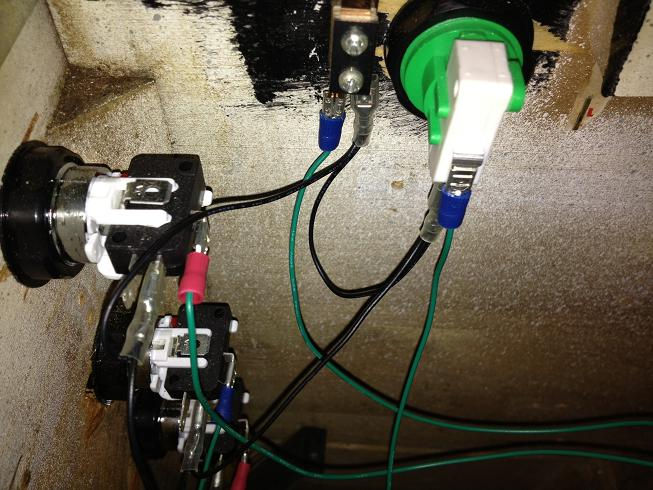
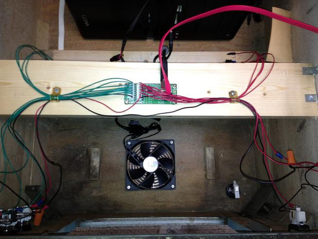
I used zip ties and cable clamps to make the wiring a little neater.

-
Run the ground wire from the wiring harness to the first switch in the series. Connect it to the COM (common, or ground) connector on the switch. (IMPORTANT: on the Mot-Ion board, there are two connectors and, thus two wiring harnesses. Ground the switches connected to each harness to the ground connected to the same harness!)
-
Run a short ground wire from the COM connector on the first switch in the series to the ground connector on the next switch in the series and so on down the line until you reach the last button in the series. Do this in order of the connections. (Again, it doesn't matter if you didn't use every connector on the harness--just do it in order of the connected ones--1, 2, 5, 8, etc.)
Leaf switches work the same way, except they only have two connectors. I wired the ground to the outside connector closest to the inside of the cabinet and the live connection to the inside connector and it works fine. Just be consistent as to which connector you use as the ground if you have more than one leaf switch in the series.
The plunger is the easiest of the controls to wire--just plug the SATA cable into the end of the plunger and into the SATA jack on the Mot-Ion Board.
That's really all there is to it.
Power Switch Wiring
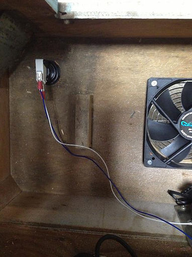
I didn't want to have to reach inside the cabinet to switch the computer on--I wanted a power switch on the outside, preferably in the same location that you'd find a power switch on an actual pinball machine. I decided to use a black arcade button for this purpose.
There is a connector on the motherboard of the computer that controls the on/off function. Actually, it's just two pins on a connector--a positive and a negative. If you are wiring directly to the motherboard, you'll want to build a connector that can plug into the motherboard.
However, if you have a case for your computer, you already have the connector you need, wired to the on/off switch on the case. I simply cut and stripped these wires and spliced them together with two wires off of my arcade button (negative from the COM and positive from the NO) using wire nuts. It worked like a charm. To switch on the PC, all I have to do is reach under the cabinet and press the button.

Wiring the Lighted Buttons
I had done some button wiring in the past (when I built my JAMMA multi-game control panel, but I had never wired lighted buttons prior to this project.
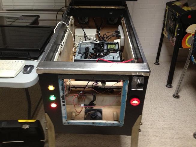
According to my online research, lighted buttons need +5 volt power to operate. A computer power supply has both +5 and +12 volt power output. I had plenty of free power connectors on my PC (even after connecting the fans) so I simply used one of them to power my 3 LED buttons and the Ball Launch button (which has a light bulb).
The power connector I used was a 4-pin connector with a +5v, a +12v, and 2 ground connections (same connector type that the fans use). The power supply manual has a pin-out of each connector so you can tell which color wire is which.
I got a matching male connector and wiring harness (a hard drive power cable splitter--I wanted something that was pre-wired). On the splitter harness, I removed the wires for the +12 and the ground next to it. (I thought it was better than hacking the harness on the power supply itself...) I stripped the +5 and ground on the splitter harness and I was ready to go.
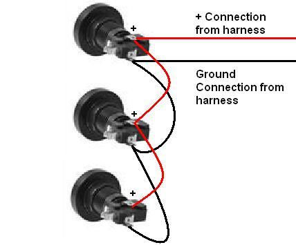
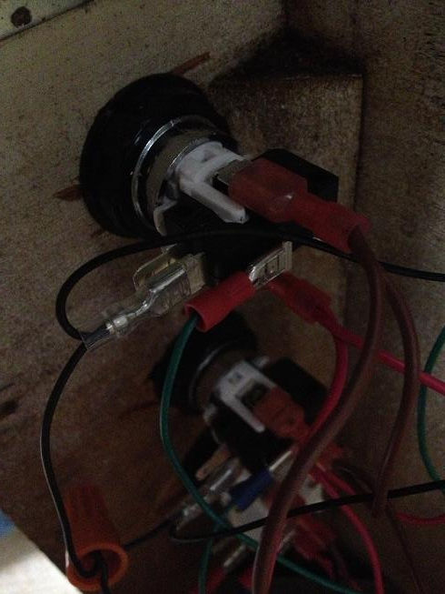
I've made you another handy-dandy diagram that you can use as a guide (see the photo gallery). Basically, you just have to connect the positive and ground wires from the harness to the positive and negative terminals on the first lighted switch (these are separate connectors from the micro-switch button connections and the positive terminal is labeled with a "+"). Then, daisy-chain the positive and negative connections from one button to the next until they're all connected to the series.
Once again, use crimp-on quick disconnects to make your life easier. The LEDs and lights use a larger version than the buttons themselves--3/16".
It's worth noting that this wiring technique produces lighted buttons that are always on. If you want them to flash, you'll need an LED controller board like the LED-WIZ or the PacLED. (2020 note: I just got that Star Trek reference. Well played.)
The lighted buttons look really cool...cool enough so that I might, someday, consider replacing some of the regular buttons with lighted ones.